By identifying jitter and noise impacts you can quickly make design improvements. Set plotting mode to append.
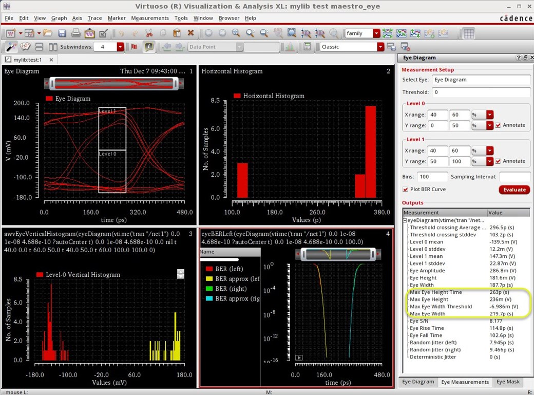
Virtuosity New Eye Diagram Measurements Custom Ic Design Cadence Blogs Cadence Community
A VCO model in Verilog-A is presented and a step-by-step guide to transient reponse and jitter calculation using Cadence Virtuoso IC616 is provided.
. Oscillator Simulation on Cadence 6 About Press Copyright Contact us Creators Advertise Developers Terms Privacy Policy Safety How YouTube works Test new features 2022. Setup S-Parameter analysis as described above in 21. One models jitter in a signal by starting with a noise-free signal xt and displacing time with a stochastic process jt.
If Monte Carlo simulation for different seed is required then. Moreover a brief overview of the eye diagram is given. In this tutorial the procedure for doing noise analysis in ADEL is explained.
I did not say i calculated jitter from time 0usi entered the jitter from the time of lock to the end of transient simulation timehere when u the tool asks u to enter the average time period u click the output signal and then calculate the average using the calculatori said doing this is wrong since this value entered decides the closing of the eye in the eye diagramso just. Cadence simulation setup Normal 1. Command Interpreter Window Library Manager Window In this tutorial a simplified convention will be used to show the sequence of steps for the pull down menu.
If the VCO frequency is off the beat frequency by too much over sweeping Vctrl PSS may fail. Phase noise and jitter in digital electronics are unavoidable but you can design to minimize things like power dropout crosstalk reflections and EMI susceptibility with a complete set of system analysis tools from Cadence. In function select G.
This tutorial explains the procedure for plotting an eye diagram in Cadence. Cadence Sigrity SystemSI. This tutorial demonstrates the procedure for Post-layout simulations in Cadence and finding the number of parasitics in our layout.
Choosing affirma analog artist 2. Index Terms Jitter low-noise oscillators noise noise measure-ment noise simulation oscillators oscillator noise oscillator sta-bility phase jitter phase-locked loops phase noise phase-noise simulation voltage-controlled oscillators. Monte Carlo simulation 1Choose setup model libraries 2Browse and choose model file in the directory Cadence simulation setup Normal.
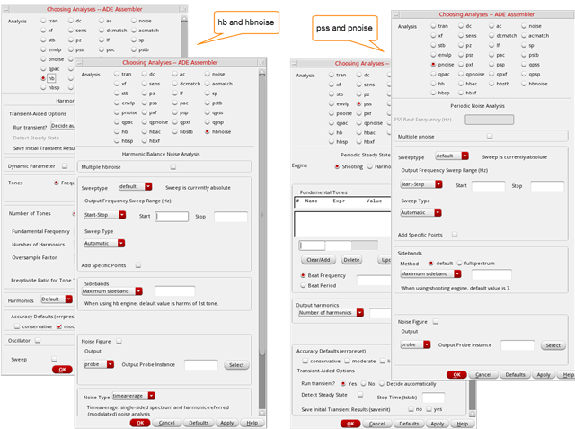
Subscribe to our newsletter for the latest updates. To calculate FM jitter for oscillators you need to select Noise typetimeaverage PM or Noise Typetimeaverage ALLAMPMUSBLSB from the PnoiseHbnoise Choosing Analyses form. Monte Carlo simulation Seed no parallel simulation Note.
1 Input file should have scs extension for exainputscs 2In spectre one can not specify different seed from GUIby default it always takes seed1. I set up a pss simulation with. The tool fully supports industry-standard IBIS AMI TX and RX models in simulations that assess the effectiveness of chip-level signal.
This tutorial provides a detailed guide to analysis and simulation of mixed-signal circuits like voltage-controlled oscillators VCOs used in clocking circuits for high-speed link applications. In analysis eld select sp. 3Jitter Jitter is an uncertainty or ra ndomness in the timing of even ts.
Simulation results for a DDR3 interface including a memory controller and SDRAM. For a first testbench I use a simple vpulse creating a rectangular 100 MHz clock and a simple CMOS inverter. In the case of our syn-thesizer the events of interest are the transitions in the output signal.
Choosing Spectre simulator Choosing model filewhich contains all MOSregcap model parameters. About Press Copyright Contact us Creators Advertise Developers Terms Privacy Policy Safety How YouTube works. Schematic Entry and Functional Simulation 2 one since it has basic circuit elements like transistors current sources voltage sources ground resistors capacitors etc.
The noisy signal becomes xnt xt jt 7. Step 1Create netlistinput file aEither from analog artist or. I generate a clock with a bunch of logic gates and flip flops and would like to assess what kind of jitter in ps rms I can expect at the output.
Make sure the VCO works by setting the Initial Condition tstab should be longer than the time the VCO needs to stable. Simulation issues and the accommodation of amplitude noise are considered in appendixes. The Noise Typejitter option only calculates PM jitter for both driven circuits and oscillators.
Click Results Direct Plot Main Form. Do tran analysis first to estimate the VCO frequency at the fixed Vctrl as the Beat frequency.
2

Cadence Ic615 Virtuoso Tutorial 18 Eye Diagram In Cadence Ic615 Youtube
Measurement Of Phase Noise In Oscillators Rf Design Cadence Blogs Cadence Community
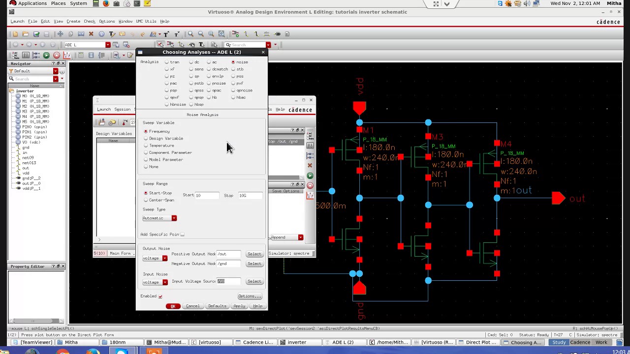
Cadence Ic615 Virtuoso Tutorial 9 Noise Analysis In Cadence Adel Youtube

Cse 493 593 Cadence Tutorial

Cadence 6 Tutorial 3 Youtube
2
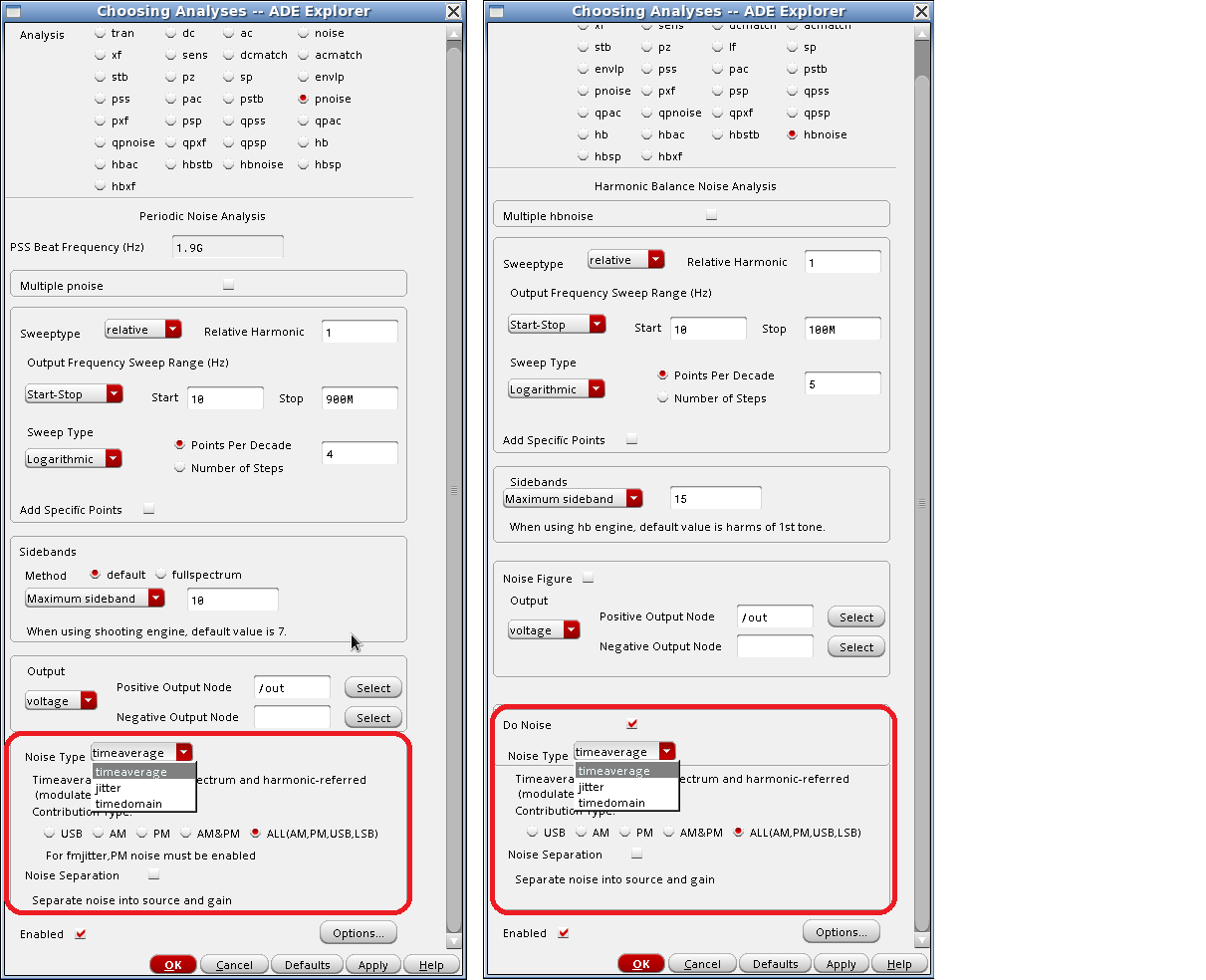
Noise Simulation In Spectre Rf Using Improved Pnoise Hbnoise And Direct Plot Form Options Rf Design Cadence Blogs Cadence Community
0 comments
Post a Comment